


Initial situation
My customer is developing a device for future DC grids that goes beyond the classic point-to-point topology. In the event of a fault, this device is designed to reduce the fault current to such an extent that a mechanical switch can electrically isolate the faulty part of the grid. Since the key components in this device, which are electrically connected in parallel, can only carry a certain current, electrical simulations were used to determine the current distribution through these components. It should be within certain limits specified by the customer.
Realisation
The current flows in the customer’s device were determined using various tools in Ansys Electronic Desktop (AEDT).
First, the CAD, data provided by the customer as a STEP file, was analyzed. For the DC simulations in Q3D, the arrangement could be greatly simplified, as only the main current path plays a role. First, the DC-RL and AC-RL solvers were used in Q3D, as this solver produces results quite quickly thanks to its special meshing. This is particularly important for complex models such as those in this case.
All parts, including the simplified key component, were assigned the material copper from the internal database. This turned out not to be ideal in the subsequent analysis, as some components have a much higher resistance than the conductors.
The specific conductivity was calculated from the characteristic curve of the key component and used to create a special material in AEDT. The DC simulation showed a uniform distribution that matched the customer’s expectations. However, the current can change significantly in the event of a fault and a uniformly distributed current should also be achieved in this case. For this reason, the AC-RL solver was also used.
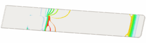
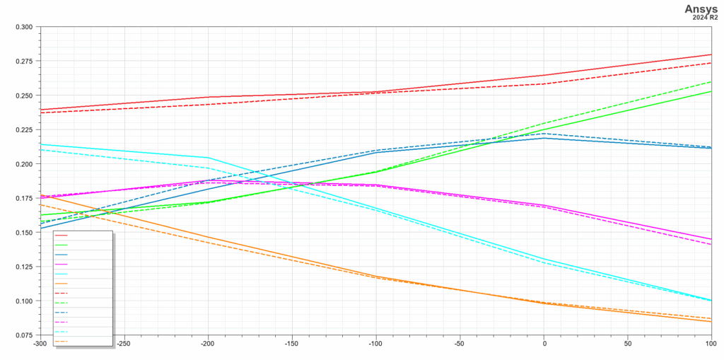
The model for the AC simulation contains almost all of the components from the original CAD design, because AC also allows for coupling due to eddy current effects on secondary current paths. In addition, the “geometry” of the key components was optimised. The AC simulation showed a pronounced non-uniformed distribution of the currents. To reduce this, the model was modified in various ways. Two geometric parameters were added to the model and a parametric study was carried out. This enabled an optimum to be found.
Since Q3D focuses on the calculation of matrices, the field simulations are only calculated in the two extremes, DC and high frequencies. High frequencies refer to a fully shaped skin effect. This means that in the AC simulation only the surfaces of the conductors are meshed, which makes the simulation with Q3D fast. However, the current distribution at low frequencies is not reproduced realistically. The Maxwell tool in AEDT is suitable for this.
The original structure and the optimised geometry from the AC simulation of Q3D were transferred to Maxwell. Here, fields and currents were calculated at different frequencies. As result the currents flow almost uniformly through the key components at frequencies below 10 kHz. Above 10 kHz the distribution was similar as calculated with Q3D.
As the expected frequencies for the device in the event of a fault are in the range of 100 Hz, it can be assumed that all of the key components have approximately the same load in the event of a fault.
Targets and key figures


December 2024 – April 2025

Budget 35’000 CHF

Independent project work

Energy technology
Testimonial
We can very well imagine working together on similar issues in the future.”