


Initial situation
Pulse generators are characterized by a high electrical and mechanical load. Most components are therefore designed at their load limits. The greatest loads occur when the generator is discharged quickly. In contrast, the loads in the slow charging phase are low.
Typical pulse generators have a Marx design that produces high discharge voltages from low charge voltages. In this setup, the discharge circuit is complex in design and includes many components that can fail due to the high load.
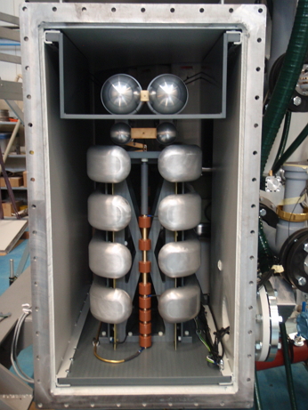
In most high-voltage pulse generators, the switching elements are gas spark gaps. They are located inside the generator. To make the generator as compact as possible, it is filled with insulation oil. This requires a good seal between gas and oil, because the gas is usually under pressure. The seals are subject to mechanical stresses and can lead to insulation failure during prolonged operation.
Implementation
First, I commissioned basic analyses of various generator principles from two independent research institutes. From this, I have designed a concept that reduces the complexity of the highly loaded discharge circuit and increases that of the less loaded charging circuit in return. In this way, the number of stressed components could be significantly reduced.
Since the charging circuit has a much higher output voltage than Marx generators, it was completely redesigned in collaboration with the University of Applied Sciences of Western Switzerland. It consists of a DC link converter, a transformer for 20 kHz with an output voltage of 100 kV and a cascade to generate the output voltage of 250 kV. The charging cycle had to be completed within 20 ms, which required a charging power of 30 kW.
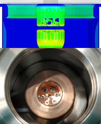
The cascade was designed in my team with the help of simulations. The space available for the cascade was very limited, so the design had to be optimized.
Using a novel concept, I separated the spark gap area (gas insulated) from that of the pulse capacitors (oil insulated). I used simulations to determine the exact design of the spark gap. This alleviated the leakage problem and extended the service life of the spark gap by a factor of 10.
The new generator proved to be very reliable in the test. At the same time, a cost reduction could be achieved compared to the predecessor models. I was able to meet the ambitious framework conditions of the project.
Targets and key figures


July 2012 – September 2013

Budget 1’000’000 CHF

Seven employees in the team

Mechanical and electrical industry

Patent application
Testimonial
